Using Bend Deductions
The machine reuses saved bend deductions during die bending. The customer can save their own values. The correction factor k, the bend deduction and the inner radius are interconnected by means of a formula.
The following applies:
-
If the correction factor k changes, the bend deduction changes as well.
-
If the bend deduction changes, the correction factor k changes as well.
-
If the inner radius changes, the bend deduction changes. However, the correction factor k remains unchanged.
Scenarios
Own bend deductions can be manually entered or imported into this screen.
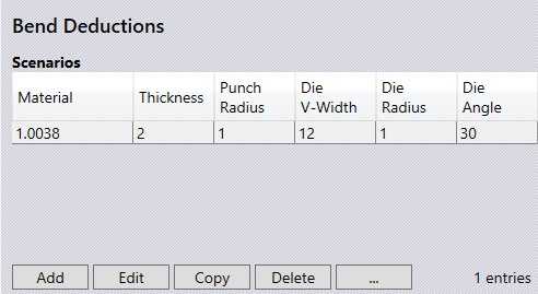
Material - Displays the material for which the scenario applies.
Thickness - Displays the thickness of the sheet to which the scenario applies.
Punch Radius - Displays the upper tool radius for which the scenario applies.
Die V Width - Displays the lower tool width for which the scenario applies.
Die Radius - Displays the lower tool radius for which the scenario applies.
Die Angle - Displays the lower tool angle to which the scenario applies.
Add - Use this switch to add a Scenario.
Edit - Use this switch to allow editing of the selected scenario.
Copy - This will copy the information of the selected scenario, allowing editing and adding as a new scenario.
Delete - This option will delete the selected scenario.
Graph… - Displays the Deduction graph screen.
Reset - This will delete all custom bend deduction data.
Import… - Bend deductions can be imported here using a CSV file.
Export… - Bend deductions can be exported here using a CSV file.
| This does not work with Trumpf bend deductions. |
Air Bending
To add bend deductions for air-bending, select a suitable scenario that the deduction will apply. This will highlight the Add menu.
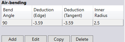
Bend Angle - Displays the bending angle for the bend deduction.
Deduction (Edge) - Displays the bend edge deduction for the selected scenario.
Deduction (Tangent) - Displays the tangent bend deduction for the selected scenario.
Inner Radius - Displays the inner radius set for the selected scenario.
Add - Use this switch to add a bend deduction.
Edit - Use this switch to allow editing of the selected bend deduction.
Copy - This will copy the information of the selected Air-bending deduction, allowing editing and adding as a new deduction.
Delete - This option will delete the selected deduction.
Coining
To add bend deductions for coining, select a suitable scenario that the deduction will apply. This will highlight the Add switch.
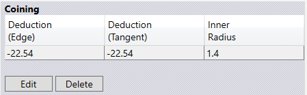
Deduction (Edge) - Displays the bend edge deduction for the selected scenario.
Deduction (Tangent) - Displays the tangent bend deduction for the selected scenario.
Inner Radius - Displays the inner radius set for the selected scenario.
Add - Use this switch to add a bend deduction.
Delete - This option will delete the selected deduction.